Full Adder Circuit Diagram Using Nand
Decoder adder using nand gates implement circuit active low outputs logical comment add link Adder schematic nand circuit Patents claims
Lab
Adder nand implementation nutshell instrumentation 10+ adder circuit diagram Patent us8405421
Design full adder using 3:8 decoder with active low outputs and nand gates.
Adder bit nand using circuit circuitlab descriptionInstrumentation in a nutshell: implementation of half adder with nand gates Adder subtractor bit make carry ripple verilog circuit binary diagram using 4bit want geeksforgeeks output hdl has sourceFull 1 bit adder using nand.
Full adder using nand .


10+ Adder Circuit Diagram | Robhosking Diagram

Full 1 Bit Adder using NAND - CircuitLab
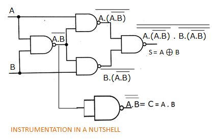
INSTRUMENTATION IN A NUTSHELL: Implementation of Half Adder with NAND gates

Lab

Design full adder using 3:8 decoder with active low outputs and NAND gates.

FULL ADDER USING NAND - Multisim Live