Full Wave Bridge Rectifier Schematic Diagram
Full wave bridge rectifier operation Full wave bridge rectifier – circuit diagram and working principle Rectifier wave bridge electric diagram schematic illustration circuits volume lessons
Full Wave Rectifier-Bridge Rectifier-Circuit Diagram with Design & Theory
Full-wave bridge rectifier Rectifier circuit diagram Full wave bridge rectifier with capacitor filter design calculation and
Schematic diagram of full-wave bridge rectifier.
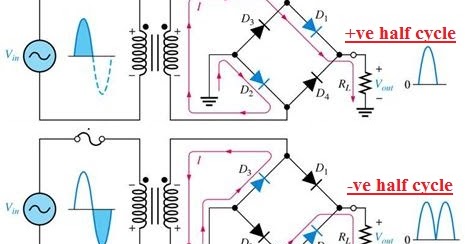
Rectifier wave bridge circuitRectifier diode input diodes biased d1 กระแส ไดโอด engineeringtutorial Rectifier transformer tapped waveformFull wave bridge rectifier circuit.
Electrical page: bridge full wave rectifierFull wave bridge rectifier circuit Rectifier waveform capacitor signal resistor circuitglobe disadvantagesFull wave bridge rectifier.

Rectifier diode capacitor circuitstoday waveform
Rectifier bridge wave capacitor filter half formula calculation flow electric positive cycle voltage shocks current waves high operation filters duringFull wave bridge rectifier with capacitor filter design calculation and Rectifier circuit bridge diagram wave working detailsRectifier bridge wave supply micro diagram digital detail.
Rectifier wave bridge circuit diagram diode voltage operation peak fig shown its below inverse value disadvantages advantages whenFull wave rectifier-bridge rectifier-circuit diagram with design & theory Full wave bridge rectifierFull-wave bridge rectifier.

Rectifier bridge wave circuit diagram power supply working regulated principle waveforms
Rectifier circuit diagram wave waveform output inputHalf wave & full wave rectifier: working principle, circuit diagram Rectifier bridge wave capacitor filter circuit diagram schematic diode voltage output calculation formula diodes input shocks electric choose board operationFull wave bridge rectifier – circuit diagram and working principle.
Rectifier circuit diagramRectifier bridge wave operation circuit waveform half negative end becomes cycle shown below during positive figure disadvantages advantages Rectifier bridge circuit wave diagram regulator icFull wave bridge rectifier.
Rectifier bridge diagram circuit wave construction principle working
Rectifier circuit output principleFull wave bridge rectifier Rectifier bridge waveFull wave bridge rectifier supply.
Rectifier input principle rectifiers theory .


Full Wave Bridge Rectifier – Circuit Diagram and Working Principle

Full-wave Bridge Rectifier | Discrete Semiconductor Circuits

Full Wave Rectifier-Bridge Rectifier-Circuit Diagram with Design & Theory

Full Wave Bridge Rectifier Circuit

Full Wave Bridge Rectifier Operation - Engineering Tutorial

Full Wave Bridge Rectifier – Circuit Diagram and Working Principle

full-wave-bridge-rectifier - Electronic Circuits and Diagrams

Full-Wave Bridge Rectifier - YouTube